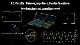
In physics and engineering, a phasor (a portmanteau of phase vector) is a complex number representing a sinusoidal function whose amplitude (A), angular frequency (ω), and initial phase (θ) are time-invariant. It is related to a more general concept called analytic representation, which decomposes a sinusoid into the product of a complex constant and a factor depending on time and frequency. The complex constant, which depends on amplitude and phase, is known as a phasor, or complex amplitude, and (in older texts) sinor or even complexor. A common situation in electrical networks powered by time varying current is the existence of multiple sinusoids all with the same frequency, but different amplitudes and phases. The only difference in their analytic representations is the complex amplitude (phasor). A linear combination of such functions can be represented as a linear combination of phasors (known as phasor arithmetic or phasor algebra) and the time/frequency dependent factor that they all have in common. The origin of the term phasor rightfully suggests that a (diagrammatic) calculus somewhat similar to that possible for vectors is possible for phasors as well. An important additional feature of the phasor transform is that differentiation and integration of sinusoidal signals (having constant amplitude, period and phase) corresponds to simple algebraic operations on the phasors; the phasor transform thus allows the analysis (calculation) of the AC steady state of RLC circuits by solving simple algebraic equations (albeit with complex coefficients) in the phasor domain instead of solving differential equations (with real coefficients) in the time domain. The originator of the phasor transform was Charles Proteus Steinmetz working at General Electric in the late 19th century. Glossing over some mathematical details, the phasor transform can also be seen as a particular case of the Laplace transform, which additionally can be used to (simultaneously) derive the transient response of an RLC circuit. However, the Laplace transform is mathematically more difficult to apply and the effort may be unjustified if only steady state analysis is required. (Wikipedia).
Electrical Engineering: Ch 10 Alternating Voltages & Phasors (8 of 82) What is a Phasor?
Visit http://ilectureonline.com for more math and science lectures! In this video I will explain how to represent a phasor on a phasor diagram in rectangular, polar, or exponential form. Next video in this series can be seen at: https://youtu.be/ZrXud82vfQc
From playlist ELECTRICAL ENGINEERING 10 PHASORS, PHASOR DIAGRAMS IN RCL CIRCUITS
Electrical Engineering: Ch 10 Alternating Voltages & Phasors (12 of 82) Time vs Phasor Domain
Visit http://ilectureonline.com for more math and science lectures! In this video I will explain the difference between the domain and the phasor domain. The domain represents a sinusoidal voltage as a function of time. The phasor representation represents a snapshot of the phasor at ti
From playlist ELECTRICAL ENGINEERING 10 PHASORS, PHASOR DIAGRAMS IN RCL CIRCUITS
Electrical Engineering: Ch 10 Alternating Voltages & Phasors (15 of 82) Differences Summarized
Visit http://ilectureonline.com for more math and science lectures! In this video I will explain the differences between the time domain and the frequency domain of alternating voltages and the phasor expressions. Next video in this series can be seen at: https://youtu.be/HYEEn_gMgfs
From playlist ELECTRICAL ENGINEERING 10 PHASORS, PHASOR DIAGRAMS IN RCL CIRCUITS
Electrical Engineering: Ch 10 Alternating Voltages & Phasors (22 of 82) Phasor Diagram for Resistors
Visit http://ilectureonline.com for more math and science lectures! In this video I will show how to draw a phasor diagram for resistors and how to convert current from the time domain to frequency domain. Next video in this series can be seen at: https://youtu.be/Jdx2jAURY4M
From playlist ELECTRICAL ENGINEERING 10 PHASORS, PHASOR DIAGRAMS IN RCL CIRCUITS
Electrical Engineering: Ch 10 Alternating Voltages & Phasors (23 of 82) Phasor Diagram for Inductors
Visit http://ilectureonline.com for more math and science lectures! In this video I will show how to draw a phasor diagram for inductors and how to convert voltage from the time domain to frequency domain. Next video in this series can be seen at: https://youtu.be/N25bT1QjmQI
From playlist ELECTRICAL ENGINEERING 10 PHASORS, PHASOR DIAGRAMS IN RCL CIRCUITS
Three phase electric power and phasor diagrams explained
Electricity and Three phase power: Voltage and current "Line to Neutral", "Line to Line", and Phasor Diagrams. My Patreon page is at https://www.patreon.com/EugeneK
From playlist Physics
Electrical Engineering: Ch 10 Alternating Voltages & Phasors (13 of 82) Phasor Transformation
Visit http://ilectureonline.com for more math and science lectures! In this video I will explain how to calculate a phasor transformation between the sine and cosine functions using a phase angle. Next video in this series can be seen at: https://youtu.be/jhOA0ejtBpg
From playlist ELECTRICAL ENGINEERING 10 PHASORS, PHASOR DIAGRAMS IN RCL CIRCUITS
Which Incapacitating Agent is the Most Effective?
This time, we're ranking incapacitating agents! The term incapacitating agent is defined by the United States Department of Defense as: "An agent that produces temporary physiological or mental effects, or both, which will render individuals incapable of concerted effort in the performance
From playlist Chemistry Tierlists
Electrical Engineering: Ch 10 Alternating Voltages & Phasors (24 of 82) Phasor Diagram, Capacitors
Visit http://ilectureonline.com for more math and science lectures! In this video I will show how to draw a phasor diagram for capacitors and how to convert currents from the time domain to frequency domain. Next video in this series can be seen at: https://youtu.be/rySvNvA-UcA
From playlist ELECTRICAL ENGINEERING 10 PHASORS, PHASOR DIAGRAMS IN RCL CIRCUITS
A.C. Circuits : Phasors, Impedance, Fourier Transform, and how Inductors and Capacitors work
SUBSCRIBE : https://www.youtube.com/c/TheSiGuyEN?sub_confirmation=1 _________________________________ Join this channel to get access to perks: https://www.youtube.com/channel/UCcTgnJE_RKa8-Qzx6lB78lg/join _______________ You can support the future videos : https://www.patreon.com/TheSiGu
From playlist AC Analysis
Electrical Engineering: Ch 10 Alternating Voltages & Phasors (10 of 82) Phasor Format of Sinusoidal
Visit http://ilectureonline.com for more math and science lectures! In this video I will explain how to represent a sinusoid in phasor format including as the real part of a complex exponential or in the form of the magnitude and phase angle. Next video in this series can be seen at: htt
From playlist ELECTRICAL ENGINEERING 10 PHASORS, PHASOR DIAGRAMS IN RCL CIRCUITS
Electrical Engineering: Ch 10 Alternating Voltages & Phasors (11 of 82) Phasor Equivalence
Visit http://ilectureonline.com for more math and science lectures! In this video I will explain the what we mean by the phasor equivalence between a phasor diagram and a sinusoidal graph. Next video in this series can be seen at: https://youtu.be/hVBccbvd_N4
From playlist ELECTRICAL ENGINEERING 10 PHASORS, PHASOR DIAGRAMS IN RCL CIRCUITS
Symmetrical Components From a New Angle #SoME2
This video explores symmetrical component theory in a way that is not presented in electrical engineering school. Starting with the history and building up 1 phase at a time, the math of symmetrical components is explained in a visual way, showing the connection back to basic geometry. The
From playlist Summer of Math Exposition 2 videos
Electrical Engineering: Ch 10 Alternating Voltages & Phasors (9 of 82) Phasor Operations
Visit http://ilectureonline.com for more math and science lectures! In this video I will explain how to execute phasor operations, including phasor addition, phasor subtraction, phasor multiplication, phasor addition, and finging the inverse, square root and complex conjugate of a phasor.
From playlist ELECTRICAL ENGINEERING 10 PHASORS, PHASOR DIAGRAMS IN RCL CIRCUITS
JEE Advanced Physics 2015 Paper 2 #2 (#4) Intensity***
Visit http://ilectureonline.com for more math and science lectures! To donate: http://www.ilectureonline.com/donate https://www.patreon.com/user?u=3236071 Four harmonic waves of equal frequencies and equal intensities I0 have phase angles 0, pi/3, 2pi/3, pi. When they are superposed, the
From playlist JEE (ADVANCED) 2015 PAPER 2 PHYSICS
How MRI Works - Part 3 - Fourier Transform and K-Space
How MRI works, Part 3 - The Fourier Transform and k-Space Part 1: https://youtu.be/TQegSF4ZiIQ Part 2: https://youtu.be/M7yh0To6Wbs FFT code: https://github.com/thePIRL/fft-code-for-fun/blob/main/FFT%20code 0:00 - Intro 1:00 - The Sinusoid and phasors 5:48 - Fourier Theory 9:05 - The Fo
From playlist Summer of Math Exposition 2 videos
Electrical Engineering: Ch 10 Alternating Voltages & Phasors (14 of 82) Phasor of Deriv. & Integrals
Visit http://ilectureonline.com for more math and science lectures! In this video I will explain how to find the phasor expressions of derivatives and integrals representing capacitors and inductors. Next video in this series can be seen at: https://youtu.be/EJ1-5yuaqdA
From playlist ELECTRICAL ENGINEERING 10 PHASORS, PHASOR DIAGRAMS IN RCL CIRCUITS
Are we really attracted to other people through pheromones? How do they work? Turns out it's much more complicated than you might think. Join Hank Green for a fascinating look into the world of human pheromones in this new episode of SciShow! ---------- Dooblydoo thanks go to the followin
From playlist Biology
RLC Circuits (6 of 19) Series RC; An Explanation, Voltage, Impedance, Phasor Diagrams
For series RC circuits shows how to draw the voltage and impedance phasor diagrams, how to calculate the voltage of the source, the phase angle, the current through the circuit and the impedance. Share this video with the following link: https://youtu.be/wFADcgA2jGY Support my YouTube c
From playlist Electricity and Magnetism