Logic gates

Flip-flop (electronics)

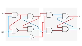
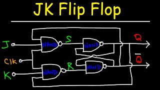
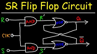
In electronics, a flip-flop or latch is a circuit that has two stable states and can be used to store state information – a bistable multivibrator. The circuit can be made to change state by signals applied to one or more control inputs and will have one or two outputs. It is the basic storage element in sequential logic. Flip-flops and latches are fundamental building blocks of digital electronics systems used in computers, communications, and many other types of systems. Flip-flops and latches are used as data storage elements. A flip-flop is a device which stores a single bit (binary digit) of data; one of its two states represents a "one" and the other represents a "zero". Such data storage can be used for storage of state, and such a circuit is described as sequential logic in electronics. When used in a finite-state machine, the output and next state depend not only on its current input, but also on its current state (and hence, previous inputs). It can also be used for counting of pulses, and for synchronizing variably-timed input signals to some reference timing signal. Flip-flops can be either level-triggered (asynchronous, transparent or opaque) or edge-triggered (synchronous, or clocked). The term flip-flop has historically referred generically to both level-triggered and edge-triggered circuits that store a single bit of data using gates. Recently, some authors reserve the term flip-flop exclusively for discussing clocked circuits; the simple ones are commonly called transparent latches. Using this terminology, a level-sensitive flip-flop is called a transparent latch, whereas an edge-triggered flip-flop is simply called a flip-flop. Using either terminology, the term "flip-flop" refers to a device that stores a single bit of data, but the term "latch" may also refer to a device that stores any number of bits of data using a single trigger. The terms "edge-triggered", and "level-triggered" may be used to avoid ambiguity. When a level-triggered latch is enabled it becomes transparent, but an edge-triggered flip-flop's output only changes on a single type (positive going or negative going) of clock edge. (Wikipedia).

Flip-flop (electronics)
Video thumbnail

Let’s Build a Vacuum Tube Toggle Flip Flop

In this episode, we take our D Flip Flop and try to turn it into a Toggle Flip Flop. There’s a really easy way to do that, but it’s never actually easy, is it? Here’s the logic diagram: https://i.postimg.cc/V62MngLs/GDFF-Logic.jpg Here’s the schematic: https://i.postimg.cc/0jmSfSbY/GDFF-S

From playlist Vacuum Tube Logic

Video thumbnail

Latches and Flip-Flops 6 - The JK Flip Flop

This is the sixth in a series of computer science and electronics lessons about latches and flip-flops. In particular, this video covers the JK flip flop, which is one of the most versatile flip flops. It is widely used in shift registers, ripple counters, event detectors, frequency divi

From playlist Latches and Flip-Flops

Video thumbnail

Latches and Flip-Flops 5 – D Type Flip Flop

This is the fifth in a series of videos about latches and flip-flops. These bi-stable combinations of logic gates form the basis of computer memory, counters, shift registers, and more. In particular, this video covers the D type flip flop, that is, a master slave configured combination

From playlist Latches and Flip-Flops

Video thumbnail

Color Changing Ball : FlipFlop Ball (CG)

Flip-Flop Ball has two stable shapes. One is dodecahedral another is icosahedral.The shape can rapidly change.

From playlist CG animations

Video thumbnail

JK flip-flop racing

In this video, we build the JK flip-flop described in my previous video (https://youtu.be/F1OC5e7Tn_o) and find out it doesn't work properly. I demonstrate "racing" (aka "race around" or "race condition") in a JK flip flop. Support me on Patreon: https://www.patreon.com/beneater If you w

From playlist Building an 8-bit breadboard computer!

Video thumbnail

JK flip-flop

Check out my SR latch video first: https://youtu.be/KM0DdEaY5sY The JK flip-flop builds on the SR flip-flop by adding a "toggle" function when both inputs are 1. The S (set) and R (reset) inputs are now referred to as J (set) and K (reset) to indicate the different operation. In other wo

From playlist Building an 8-bit breadboard computer!

Video thumbnail

Electrical Engineering: Ch 19: Fourier Transform (2 of 45) What is a Fourier Transform? Math Def

Visit http://ilectureonline.com for more math and science lectures! In this video I will explain the mathematical definition and equation of a Fourier transform. Next video in this series can be seen at: https://youtu.be/yl6RtWp7y4k

From playlist ELECTRICAL ENGINEERING 18: THE FOURIER TRANSFORM

Video thumbnail

Vacuum Tube Computer P.01 – Architecture and the MC14500B

In this episode, we take our first step towards building a vacuum tube computer! There’s a lot of different architectures out there, so we take a look at one that will hopefully work well for us. This is going to be a long road with lots of speedbumps and testing along the way. It should b

From playlist Vacuum Tube Computer

Video thumbnail

JK Flip Flop - Basic Introduction

This electronics video tutorial provides a basic introduction into the operation of the JK Flip Flop circuit which uses 2 two-input NAND Gates and 2 three-input NAND Gates. The JK Flip Flop circuit is an extension of the SR latch circuit with two additional NAND gates and a clock input.

From playlist Electronic Circuits

Video thumbnail

Static electricity.

I want to help you achieve the grades you (and I) know you are capable of; these grades are the stepping stone to your future. Even if you don't want to study science or maths further, the grades you get now will open doors in the future. Get exam ready for GCSE Maths https://primrosekitt

From playlist SQA National 5 Physics. Electricity and Energy

Video thumbnail

Winter Theory School 2022: Steve Hill

Directly observing quantum spin dynamics and relaxation via electron magnetic resonance

From playlist Winter Theory 2022

Video thumbnail

Falstad Circuit Simulator

Falstad is a free online circuit simulator. This JavaScript application is a fantastic learning tool for students of computer science and electronics. It’s particularly useful if you want to learn more about combinational logic and sequential logic. Falstad allows you to assemble electroni

From playlist Latches and Flip-Flops

Video thumbnail

Building the Largest 555 Timer in the World out of Vacuum Tubes

The 555 Timer is one of the most important and prolific integrated circuits of all time. They’re incredibly cheap, can be sourced from nearly anywhere and work wonderfully. So, let’s make it markedly worse in every single aspect! It’s huge, it consumes a ton of power, it wasn’t cheap by an

From playlist Vacuum Tube Logic

Video thumbnail

Vacuum Tube Computer P.09 – Building the 4-bit Instruction Register

Straight up, this is the coolest looking piece of electronics I’ve ever built! It looks awesome, it works great, I couldn’t be happier. So, come along as we go through the journey of building the first finalized part of our vacuum tube computer. Also, check out these episodes I reference:

From playlist Vacuum Tube Computer

Video thumbnail

SR Flip Flop Display: Part 2 – Finalizing the Vacuum Tube Design and Building it on a PCB

(This video only has one channel of audio working, please watch the re-upload for both the left and right audio channels here: https://youtu.be/tZ0V-abSNOE) In this episode, we finish building the SR Flip Flop / 1-bit Memory Display piece that we started working on in the previous episo

From playlist Vacuum Tube Logic

Video thumbnail

SR Flip Flop Display: Part 2 – Finalizing the Vacuum Tube Design and Building a PCB (FIXED AUDIO)

(This is a re-upload of my previous video with the both the left and right audio channel working now.) In this episode, we finish building the SR Flip Flop / 1-bit Memory Display piece that we started working on in the previous episode. The first step is figuring out a good way to power t

From playlist Vacuum Tube Logic

Video thumbnail

Vacuum Tube Computer P.24 – Building SR Flip Flops with Trial and Error

Now that we’re getting closer to the design for the RAM on the vacuum tube computer, let’s take a quick look at some of the different types of memory I tried to implement. It was a long journey with a lot of trial and error, but I think there were some genuinely good ideas in here that cou

From playlist Vacuum Tube Computer

Video thumbnail

SR Flip Flop Circuit With NAND and NOR Gates

This electronics video tutorial discusses the operation of the SR flip flop circuit which is composed of NAND and NOR gates. The output Q only changes with an active clock signal.

From playlist Electronic Circuits

Video thumbnail

The 60-year-old Navy platform that flips

Have you heard of the FLIP? It’s the U.S. Navy’s Floating Instrument Platform and as its name indicates, it can actually flip. It performs 90-degree flips in order to monitor hard-to-detect systems in the open ocean without rocking around in the waves. In that sense, it’s actually a float

From playlist Engineering Wonders

Related pages

Feedback | Pulse transition detector | Finite-state machine | Sequential logic | Counter (digital) | NAND gate | AND gate | XOR gate | Logic gate | Schmitt trigger | Positive feedback | Signal | Equation | Inverter (logic gate) | De Morgan's laws | Truth table | OR gate | Race condition | Dynamic logic (digital electronics) | Bit | Zero-order hold | NOR gate | Pass transistor logic | State (computer science)